
COPASI can read and display layout information from both COPASI and SBML files. A key feature is the ability to animate diagrams using simulation time course data. Layout information may be imported via the SBML Layout extension (see the SBML Layout Extension Specification for details) or obtained from a COPASI file that already contains a diagram layout.
COPASI provides a force-directed layout algorithm to arrange network diagrams automatically. To generate a new layout for your loaded model, select Model → Diagrams from the tree, and click the New button in the list of layouts.
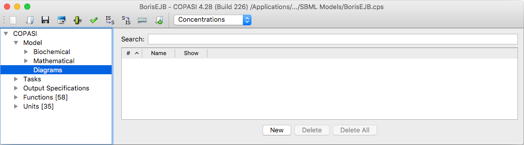 |
| Empty list of Diagrams |
When you click New, a wizard appears that lets you select which metabolites and reactions to include in your layout. If you check the create compartment elements option, a graphical representation of compartments will also be added. The next page of the wizard allows you to specify side-compounds: any metabolites you select here will be duplicated in the diagram for each reaction they participate in, helping to produce a cleaner, less cluttered layout.
After you complete the wizard, the automatic layout algorithm starts and you will see the drawing improve in real time. When the layout process finishes, you can manually reposition any elements as needed to achieve your preferred arrangement. Pressing the Play button on the toolbar restarts the layout algorithm from the current positions. If you’d like to adjust how the arrangement is computed, use Layout Parameters from the View menu. To shuffle all element positions randomly, click the Dice button.
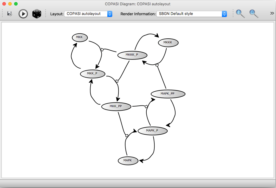 |
| Generated Autolayout |
The Save button allows you to export the current diagram as a PDF, SVG, or PNG image. The Layout drop-down menu lets you switch between different layouts stored in the file. For each layout, the Render Information drop-down provides several alternative styles for displaying the diagram.
There are several ways to obtain or create layout information for an SBML model:
If your loaded model file contains layout information, the diagram table will show one entry for each available layout. To display a specific layout, either click the Show button next to the layout entry or double-click on the entry in the table.
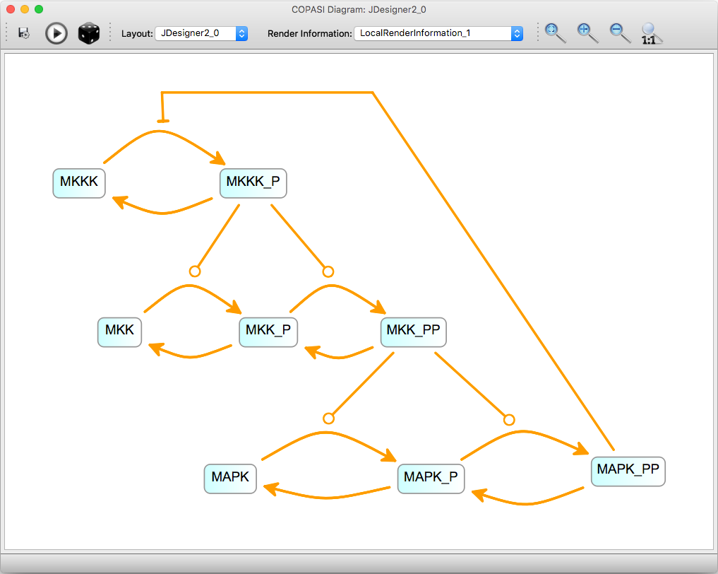 |
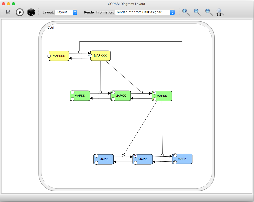 |
| Layout from SBML Layout / Render Extension, as exported by JDesigner and SBW | Imported layout from CellDesigner Annotations |
You can visualize the results of Time Course Simulations, Elementary Modes, and Mass Conservation Analysis directly on the network diagram. Before these results are available for display, you must first run the corresponding analysis task. For time courses, ensure that the option to keep results in memory is enabled.
If there is no available time course data, a warning will appear in the status bar of the layout window.
To load data after running a task, select the relevant option from the file menu within the layout window. On systems with a unified toolbar, you may first need to activate the layout window to ensure you are using its file menu, rather than COPASI’s main file menu. Once data is loaded, video player-style controls will appear at the bottom of the layout window. Click the play button to start the animation.
 |
| Time series result on top of an autogenerated layout, color mode |
You can zoom and pan within the network diagram and reposition elements as needed. In the preferences menu, you can set how each individual element should be animated. The available animation modes are:
For all animation modes, scaling can be set to either Global or Individual:
 |
| Time series result on top of an imported layout, scale mode |
We plan to improve visualization features in the future. If you have suggestions or feedback, please let us know—preferably through the User Support Forum. If you discover a bug, please report it using our Issue Tracker.